Introduction
This new Car Tracker solution is part of the Cirrus AI suite of products. The camera plugs directly into the controller, and a vendor-agnostic Camera Agent handles connected cameras.
What you need before starting
Confirm you have the right hardware and the correct power configuration for your controller version before heading to the install site. The instructions below focus on Milesight cameras, which can cover all use cases.
Hardware requirements
- Cirrus Car Tracker Camera
- Controller — A1 v2.x controller
- Ethernet cable — UTP cable for connecting camera to controller
- Power supply (if needed, for A1 v2.1 non-PoE controllers only) — 12 Vdc power supply OR Cirrus logo with 12 Vdc output, plus a DC power cable
Power options by controller version
A1 v2.2
The LAN port has PoE support, so the ethernet cable carries both data and power for the camera connection. Single cable, no additional connections needed.
A1 v2.1
Camera ethernet connects to the controller, but an additional 12 Vdc power feed is required to power the camera. This feed can be drawn from the Cirrus logo or from a separate breaker.
T1
Currently not supported, but support is technically possible. We cannot integrate PoE into the T1 controller, so it would work like the non-PoE A1 controller (A1 v2.1).
Physical installation
Mount the camera, run the cable to the controller, and verify the link is live before moving on to software preparation.
Mount the camera
Mount the camera following the Cirrus assembly SOP for the sheet metal frame and Milesight's positioning guidelines for the camera model in use.
Milesight AI Road Traffic Pro Bullet Plus — models TS4466-X4RPE and TS8266-X4PE. The positioning values below apply to these models specifically. Cable: 47-0094 Cable — PoE RJ45 32.8 ft for Car Tracker.
Recommended positioning (TS4466-X4RPE / TS8266-X4PE)
| Setting | Height | Width | Length | A1 · Horizontal tilt angle | A2 · Vertical pitch angle |
|---|---|---|---|---|---|
| Recommended | 10–20 ft | 0 ft | 65.6 ft | 0° | 10°–20° |
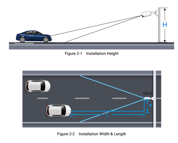
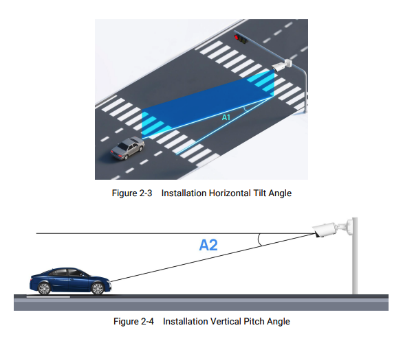
- Aim the camera as head-on to license plates as possible. The video feed should face oncoming or departing plates as squarely as possible — keep the horizontal tilt angle (A1) close to 0° and avoid side-on views, which reduce read accuracy.
- Ensure the camera has a clear view of the traffic lane
- Consider lighting conditions (direct sunlight, shadows, night lighting)
Position on the enclosure (Cirrus assembly SOP)
- Align the cameras with the designated mounting positions on the left or right sides of the main enclosure. Recommended installation height: ~10-20 ft.
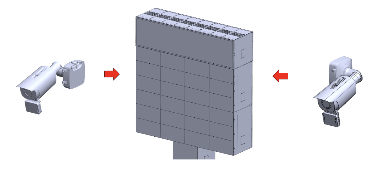
- Secure and mount the cameras firmly onto the sides of the enclosure following the assembly steps below.
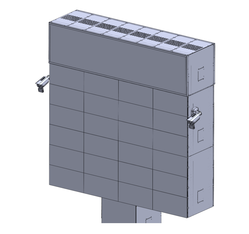
- Connect the 47-0094 RJ45 PoE network cable from the controller to the side camera.
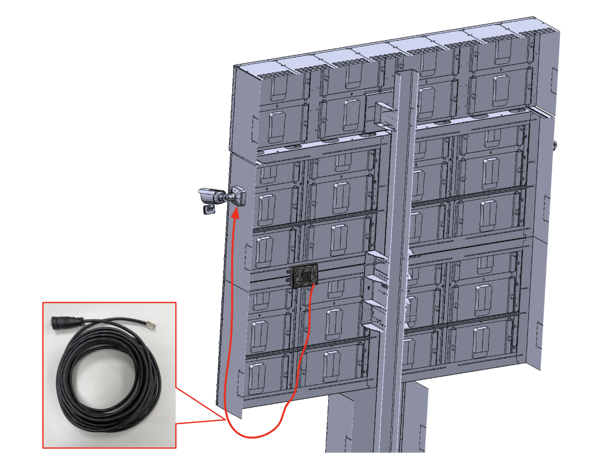
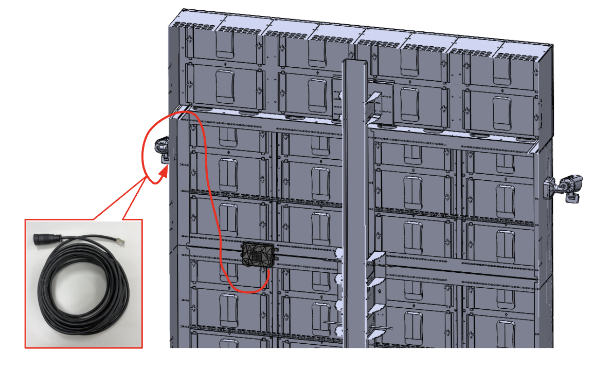
Assemble the camera and junction box
- Fix a sticker on the position where the camera is intended to be installed.
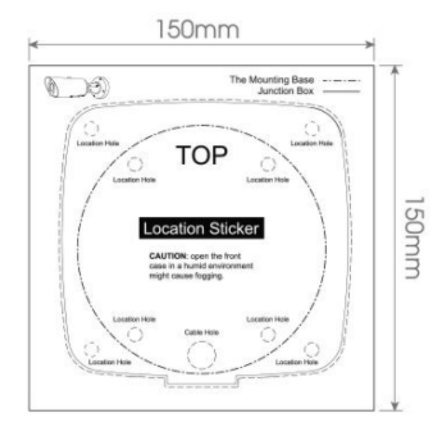
- Remove the tension disc on the rear cover of the junction box, cut an opening in the rubber plug, route the cables through the opening, then fasten the rear cover to the sticker.
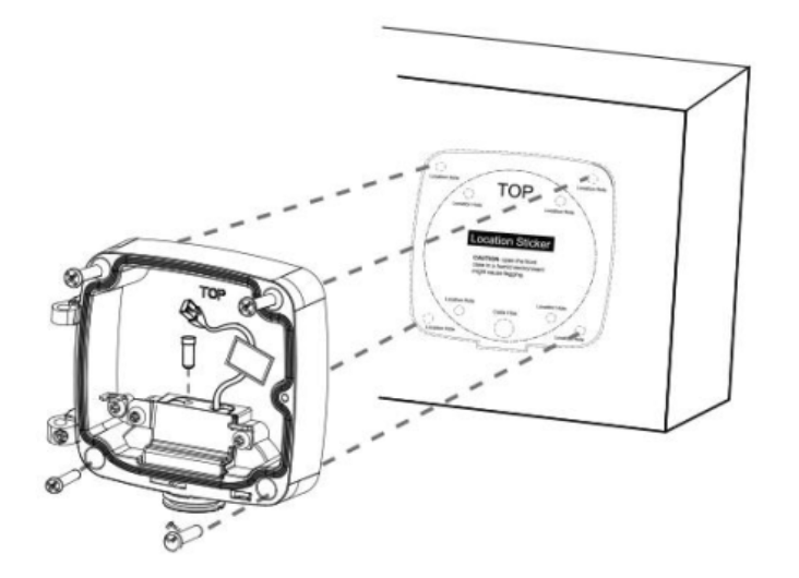
- Install the front cover at an angle near 90° to the rear cover. Pay attention to the two "Top" markings — the "Top" on the bullet must be aligned to the "Top" on the junction box.
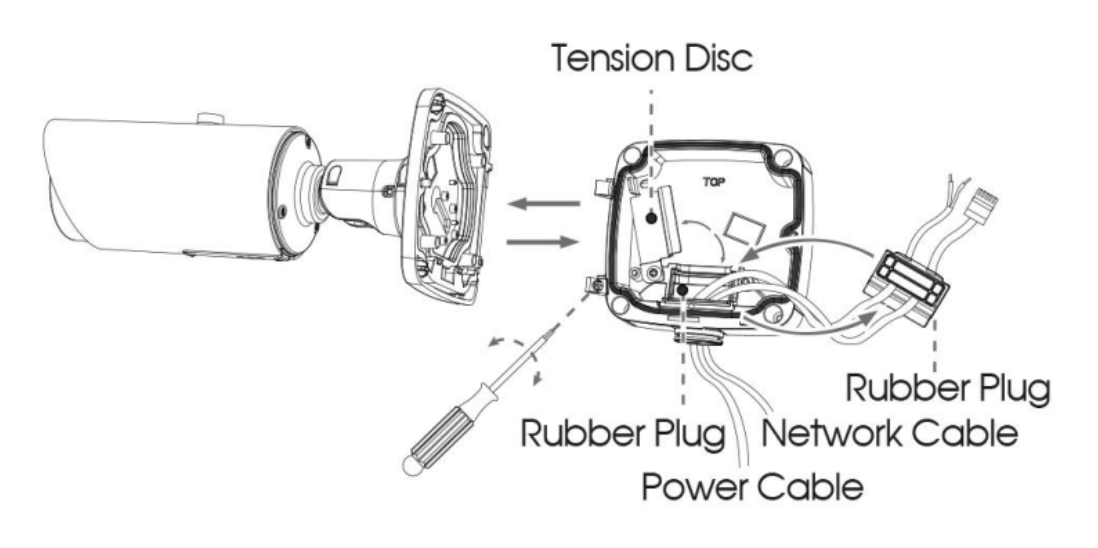
- Adjust the cable length, connect the cables to the corresponding interfaces, and fix the tension disc. Close the junction box and fix the screws last. Plug the small rubber plug into any hole on the rubber plug that is not in use.
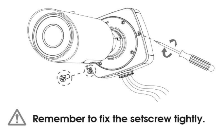
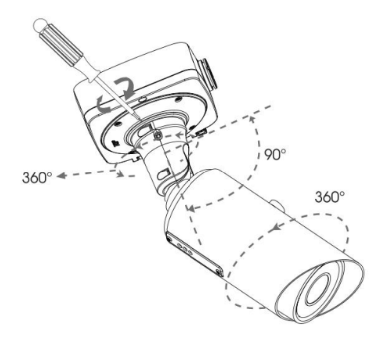
- Adjust the shooting direction and fix the setscrew.
Minimum image requirements for license plate recognition
Milesight requires all field deployments to meet these image quality standards for reliable recognition:
- Plate height: license plate characters should appear 32–45 px high in the captured image
- Focus and clarity: the plate area must be in sharp focus with all characters legible — no motion blur, glare, reflections, or severe over-/underexposure
- Alignment: plates should be horizontally aligned, with tilt within ±5°
- Framing: the plate must remain within the recognition area — not cut off, blocked, or at the extreme edges of the frame
- Environment: avoid excessive bright sky or headlight exposure; ensure the plate area is evenly illuminated day and night
For field installation on poles or corners, several optional accessories are available — see Milesight accessories.
Connect cables
For PoE controllers (A1 v2.2)
- Connect camera to controller LAN port using UTP ethernet cable
- The ethernet cable provides both data and power — no additional connections needed
For non-PoE controllers (A1 v2.1)
- Connect camera to controller LAN port using UTP ethernet cable
- Connect DC power cable from camera to one of:
- Separate 12 Vdc power supply, OR
- Cirrus logo 12 Vdc output
- Verify camera power LED illuminates
Verify physical connection
- Camera power LED should be on
- Network activity LEDs on camera and controller should show activity
- If using separate power supply, verify it is functioning correctly
Controller preparation
Using Screenhub Control Selective Field Upgrade (SFU), install the Camera Agent and Local Web Server and upgrade the Screenhub Player. Then complete the camera's first-time activation and reboot.
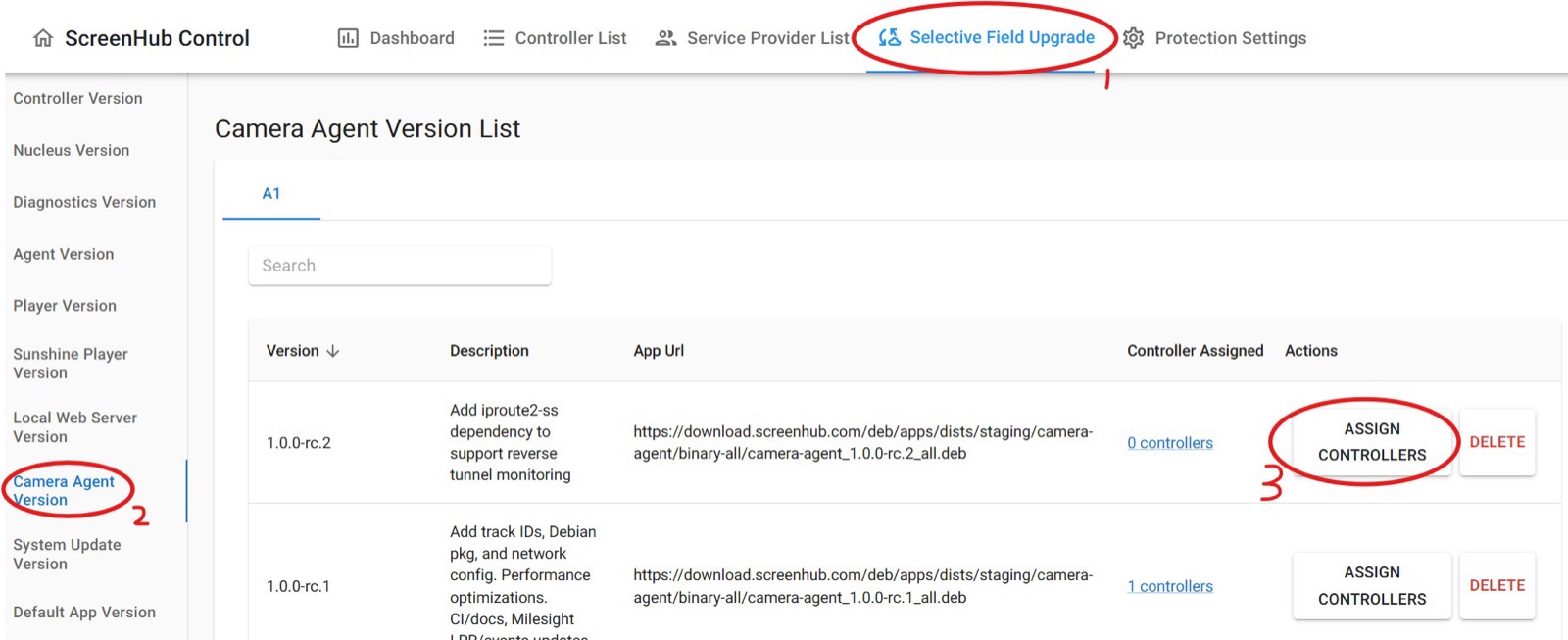
Install required software
- Install Camera Agent
- Install Local Web Server (lws) 1.6.1 or later — provides the
/camera-console/reverse proxy with Milesight auto-activation / auto-login, plus thelws-accesscommand for temporary LAN enable/disable used in Initial camera configuration - Upgrade Screenhub Player to version 5.11 or later
There is no required install order between Camera Agent and Local Web Server.
Wait for installation
Wait until all components are properly installed by SFU. This can take up to one hour.
To save time, expert users can log into the controller with webSSH and execute:
systemctl restart selective-update.service
Wait for this command to finish.
Complete first-time camera activation
Required for the first camera setup. Before rebooting, open the camera console through the Local Web Server and complete the camera's first-time activation:
- Enable temporary LAN access and open
http://<controller-hostname>.local/camera-console/— see Open the camera web interface via the controller for the exact commands. - Let the console complete the camera's first-time activation dialog. A successful login here means the camera's admin credential has been set.
- A Third-Party VMS popup appears next — click Skip (leave VMS disabled).
The auto-login script stops watching for the login page about 20 seconds after it loads and doesn't know about the VMS popup. If Skip isn't clicked in that window, the camera may not log in automatically and you'll need to log in manually.
Reboot controller
After activation, wait 1–2 minutes, then perform a soft reboot of the controller. Don't reboot immediately — the wait avoids a race condition during setup.
To reboot, log in to the controller with webSSH and run:
sudo reboot
On the next boot, the Camera Agent starts fresh, uses the correct credentials, and applies the default configuration to the camera. Once that is done, you should only need to adjust zoom, camera angle, and the region of interest.
If you open the camera console before this reboot, settings like LPR may show as disabled. This doesn't mean anything needs to be configured by hand — Camera Agent simply hasn't connected and applied its configuration yet.
Initial camera configuration
After the controller preparation steps and reboot, the Camera Agent applies the default configuration and the controller automatically registers the connected camera to Screenhub. Open the camera web UI through the controller's local web server and fine-tune the view.
Open the camera web interface via the controller
The camera's web UI is reachable through the controller's local-web-server (lws), which proxies the camera console and handles login automatically. You do not need to know the camera password.
The controller must be running Local Web Server (lws) 1.6.0 or later — earlier builds do not provide the /camera-console/ proxy with auto-activation / auto-login, or the lws-access command used below.
-
Enable temporary LAN access on the controller. Log in to the controller with webSSH and run:
bashThis opens lws on the controller's LAN interface and registers an auto-revert timer; it also auto-reverts on reboot.
sudo lws-access enable --duration 30min
-
From any device on the same LAN, open
http://<controller-hostname>.local/camera-console/.<controller-hostname>is the controller's hostname (typically the controller ID, e.g.c1234). The camera UI appears directly — lws completes the Milesight first-time activation dialog the very first time and auto-fills credentials on every subsequent visit. -
When you are done, revoke LAN access early (optional):
bashOtherwise it auto-reverts when the duration expires.
sudo lws-access disable
LAN access is intentionally short-lived. The controller normally binds lws to localhost only and exposes it to operators through the ScreenHub Control reverse SSH tunnel. sudo lws-access enable is a field-service escape hatch.
Automatic configuration
After the post-activation reboot, the Camera Agent automatically configures the camera. It applies these values every time it connects — at service startup and on every reconnect — not just once during setup.
If you change any field below by hand in the camera web UI, the change persists only until the next connect/reconnect cycle, when Camera Agent re-applies its own values.
License Plate Recognition
Traffic → LPR → General
| Field | Factory reset | Camera Agent sets |
|---|---|---|
| Enable LPR | Unchecked | Checked |
| Detection Mode | Plate Priority | Vehicle Priority |
| Repeat Plate Checktime | 4000 ms | 1000 ms |
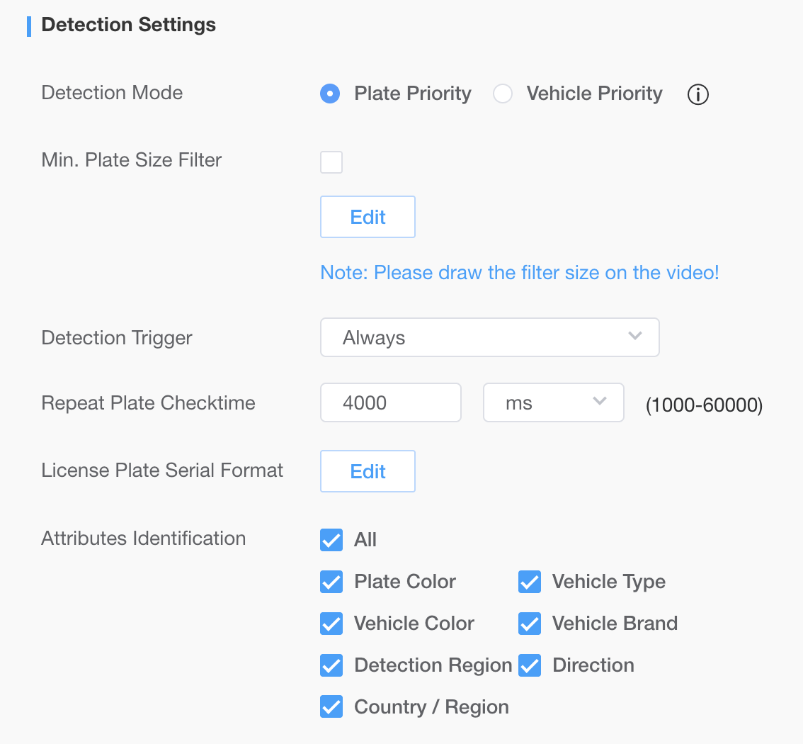
| Attributes Identification — Plate Color, Vehicle Type, Vehicle Color, Vehicle Brand, Detection Region, Direction, Country / Region | Unchecked | All checked |
Image — Day / Night Switch
Media → Image → General → Day/Night Switch — forces Day mode so plate reads stay consistent instead of drifting with the camera's IR-cut auto-switching.
| Field | Factory reset | Camera Agent sets |
|---|---|---|
| Day/Night Switch | Auto | Day |
Event Push
Data Transmission → Post → Post Settings — points the camera's HTTP event push at Camera Agent's receiver so plate events reach the agent in real time.
| Field | Factory reset | Camera Agent sets |
|---|---|---|
| Enable | Unchecked | Checked |
| URL | blank | http://192.168.5.100:8080 |
| Select Events | LPR + 6 others | LPR + 6 others (unchanged) |
System Time
System → System Setting → Date&Time — moves the camera off its own NTP sync and onto the controller's clock and timezone so plate-event timestamps convert to UTC correctly.
| Field | Factory reset | Camera Agent sets |
|---|---|---|
| Time Zone | (UTC-08:00) United States - Pacific | (UTC-05:00) United States - Eastern |
| Synchronize Mode | NTP server | Manual |
| Time | camera's own clock | controller's current local time |
| Daylight Saving Time | Automatic | Automatic (unchanged) |
Controller timezone support is currently limited to America/New_York. If the controller is set to any other timezone, Camera Agent leaves System Time untouched. The clock is synced at startup/reconnect only, not continuously.
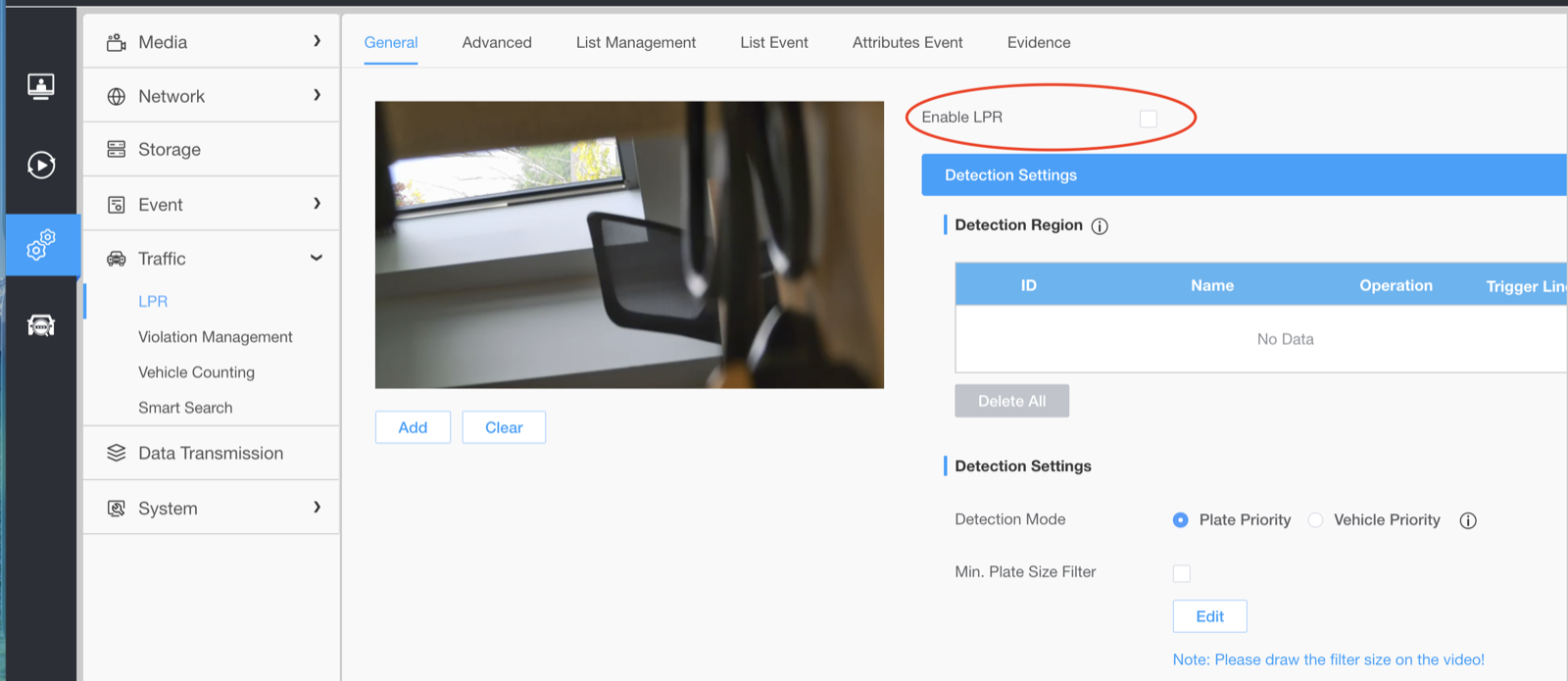
Double-check that LPR was enabled
Verify the mode was actually set, and enable it manually if not:
- In the camera web interface, click the settings wheels icon in the left sidebar
- Go to Traffic → LPR
- Check the box next to Enable LPR if it isn't already checked
Manual adjustments
Use the camera's web interface to fine-tune settings:
- Zoom level: Adjust for optimal plate visibility. Use the live view page to check zoom level and see vehicle and license plate detection in real-time. Select LPR from the stream dropdown to see the detection overlay. Use the controls on the right side to adjust zoom.
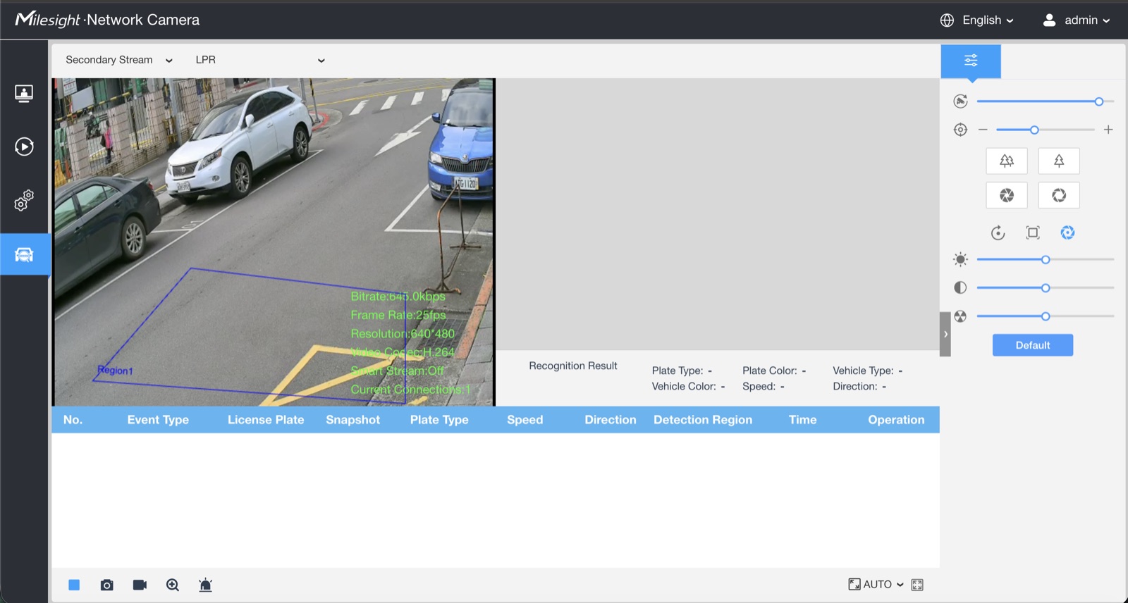
- Region of Interest (ROI): See Configure Region of Interest below for detailed instructions
Configure Region of Interest (ROI)
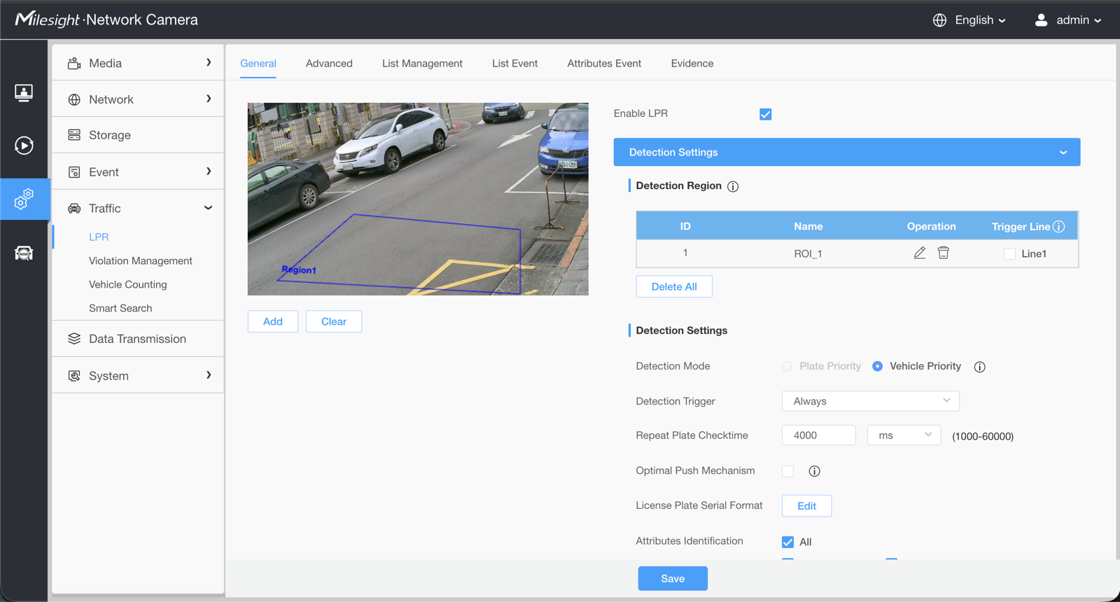
- In the camera web interface, navigate to Traffic → LPR
- On the General tab, check the Enable LPR checkbox
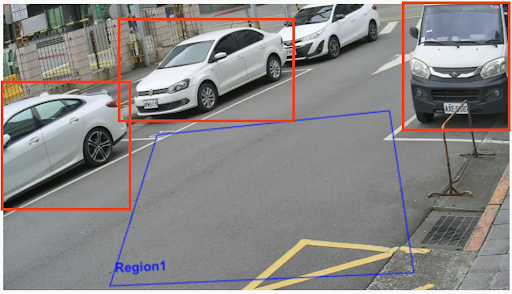
- In the Detection Region section, draw on the camera preview to select the area of interest. The selected region is shown as a blue box.
- In Detection Settings, under Attributes Identification, check the box next to All
ROI best practices
The ROI should be configured to:
- Exclude parked cars from detection
- Limit detection to a single lane
- Limit detection to a specific distance from camera
- A trigger line setting is usually not required
The image below shows an example of a poorly configured ROI — the blue region covers too wide an area, capturing unwanted detections (highlighted in red boxes) that should be excluded from the detection region:
Verify date & time settings
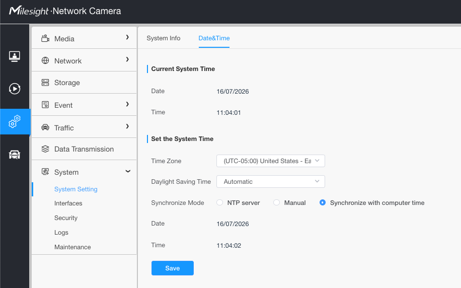
With a new installation, the time shown on the LPR page can be wrong even when the Date&Time settings look correct. You must explicitly save them once:
- In the camera web interface, navigate to System → System Setting → Date&Time
- Click Save — even if all the settings already look correct
If you don't click Save, the time on the LPR page will be wrong.
Once ROI is configured, the camera is ready.
MicroSD card
Add a Micro SD card to the Milesight camera for local storage, then format and configure it through the Local Web Server and camera page.
Prerequisites
- Micro SD card
- Physical access to the camera
- A computer (or a device) that's on the same subnet as the camera
Power off the camera
- Power off the camera completely by disconnecting the PoE network cable or the 12V DC power supply to avoid damaging the mainboard.
Open the weatherproof bottom cover
- Loosen the screw on the rain cover and slide it back or remove it.
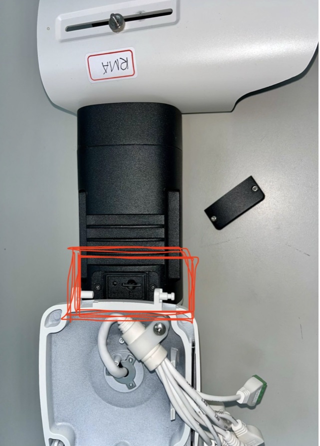
- Locate the protective plate on the underside (bottom part) of the camera body.
- Use a star screwdriver to unscrew the screws holding the bottom panel cover. Keep these screws safe.
Insert the Micro SD card
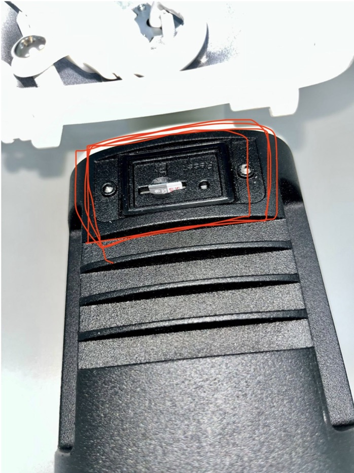
- Locate the Micro SD card slot inside the exposed chamber (see picture below).
- Refer to the picture below for the orientation of the SD card.
- Slide the card into the slot and press down until you hear a clear "click", indicating it is locked into place.
Reassemble the cover
- Put the rain cover back into its place and tighten the screw securely.
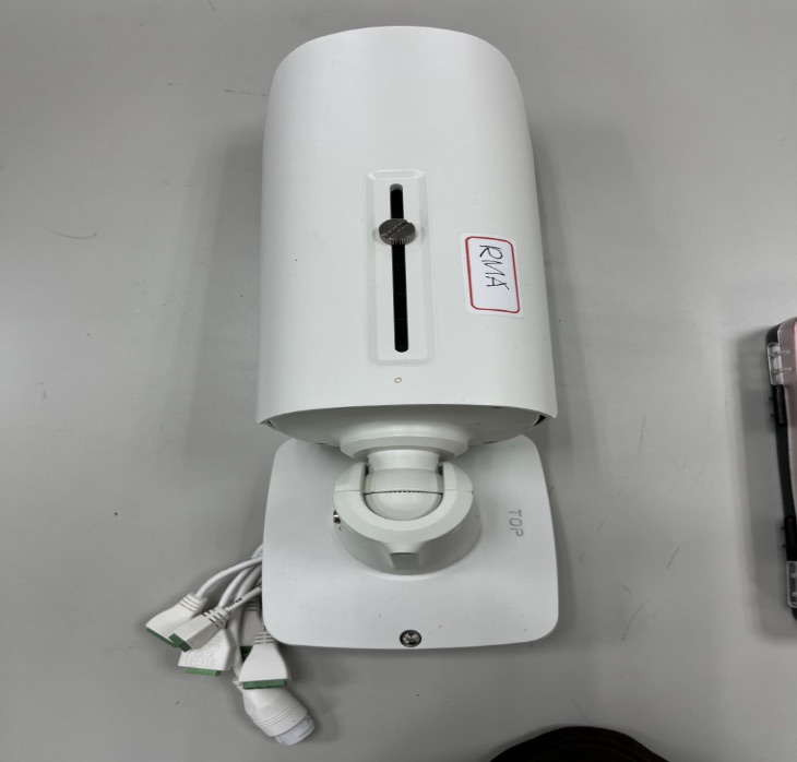
Format and configure via Local Web Server and Camera page
- Connect the camera's power/PoE cable.
- Open Local Web Server, click on Camera Access button.
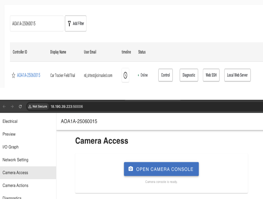
Local Web Server → Camera Access → Open Camera Console. - Navigate to Settings → Storage → Storage Management.
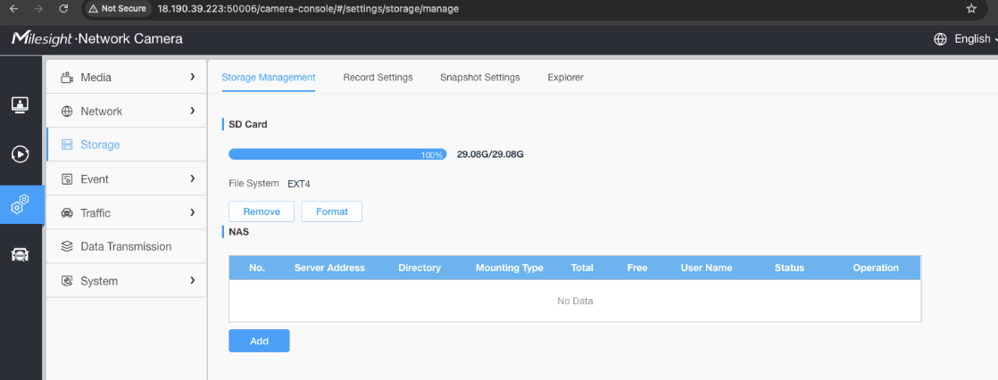
Storage → Storage Management — the SD card appears with Remove and Format options. - Select the newly installed SD card and click Format, select EXT4 and click Confirm to start formatting the SD card.
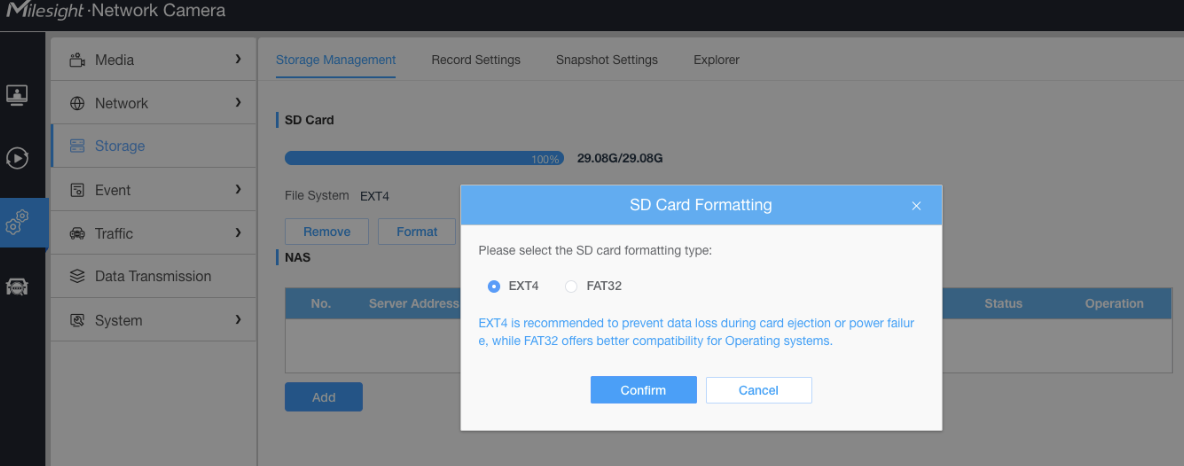
SD Card Formatting dialog — select EXT4 and click Confirm.
Troubleshooting physical installation
Common issues that show up during the physical install. Click any item to expand it.
Can't resolve an issue with the steps below? Email Cirrus Customer Support at support@cirrusled.com.
Camera not powering on
For PoE installations (A1 v2.2)
- Verify ethernet cable is securely connected at both ends
- Try a different ethernet cable
- Verify the controller's PoE port is functioning
For non-PoE installations (A1 v2.1)
- Verify DC power cable connections
- Check power supply output voltage (should be 12 Vdc)
- If using Cirrus logo, verify its 12 Vdc output is enabled
No network activity
Camera and controller LEDs show no activity
- Verify ethernet cable is securely connected at both ends
- Check for damaged cable or connectors
- Verify controller LAN port LEDs show activity
Camera not appearing in Screenhub Control
Camera connected, but Screenhub Control doesn't show it
- Verify Camera Agent software is installed (see Controller Preparation)
- Verify camera is powered and connected
- Wait a few minutes for automatic detection
- Try rebooting the controller
Camera web interface not accessible
Cannot reach the camera's web configuration pages
- Confirm LAN access is currently enabled —
sudo lws-access statusshould reportLWS LAN access: ENABLED. - Confirm the camera was detected and registered (see Camera not appearing in Screenhub Control).
- mDNS (
*.local) requires the client device to be on the same LAN and multicast not to be filtered. If<controller-hostname>.localdoes not resolve, fall back to the controller's IP address —http://<controller-ip>/camera-console/works identically. - If lws auto-login does not complete (e.g. after a Milesight firmware upgrade changes UI selectors), toggle
sudo lws-access disablethensudo lws-access enable --duration 30minand retry.